|
|
|
Kto jest w sklepie?
Sklep przegląda 5861 gości |
|
Kategorie
|
|
Informacje
|
|
Polecamy
|
|
|
 |
|
|
Dla tego produktu nie napisano jeszcze recenzji!
 ;
Schematy są ale można wysilić się i zrobić kolorowy skan i o większej rozdzielczości. Wtedy schematy płytek będą czytelniejsze. Całość super jako wartość merytoryczna. Wszystkie dane potrzebne do podłączenia różnego rodzajów urządzeń takich gramofon, CD itd.
 ;
Szybko, sprawnie i tanio. Serwis godny polecenia. Będę polecał innym
;
Ogólnie jest OK, z wyjątkiem obrazu płyty głównej, który jest miejscami mało czytelny, ale można sobie poradzić.
;
Dokładna dokumentacja, pomogła w szybkiej naprawie telewizora. Dziękuję!
;
jedyne do czego mogę mieć zastrzeżenie to jakość zdjęć zawartych w przesłanej instrukcji serwisowej ponieważ są fatalnej jakości, praktycznie nieczytelne. tak poza tym jestem zadowolony to jest to czego szukałem.
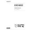
2. EACH SIGNAL FLOW
2-1. Operation at RGB Signal Input
The RGB signal is entered from PB001 on the RGB PC board and sent to the main PC board after passing through the MUTE circuit and the low pass circuit. The low pass circuit is provided to prevent a moire from occurring when the real sampling operation is not executed. Usually, a selector selects a signal not passed through the low pass filter, but selects the signal passed through the low pass filter since the real sampling is not carried out for a signal higher than SXGA85 Hz. The RGB signal entered passes through a buffer and develops PB003. In the main PC board, the RGB input signal is converted to a digital signal in A/D+PLL (QD300). The A/D converter is used in the parallel mode, so the output becomes 16 bits per 1 channel and its clock rate is a half of the sampling clock. The digital RGB signal is enlarged or reduced by the scaller (QD500) and converted into a format of fv=60Hz, panel resolution (TLP65x: 1024 x 768, TLP45x: 800 x 600). The scaller output signal is a RGB signal of 10 bits per 1 channel, converted into the analog signal by the D/A converter and fed to the drive circuit. The scaller (QD500) also performs the contrast/ brightness control and keystone correction in addition to the enlargement or reduction process for the video signal entered. The clock signal for the input system is generated in the A/D+PLL (QD300) and that for LCD panel drive system is in the 2nd PLL (QD402) circuit. In the drive circuit, the pre-driver circuit amplifies the signal and performs a gamma correction. The correction signal sent from the color uniformity correction IC (Q971) enters the BIAS control terminal of the pre-driver (Q701) and the color uniformity is corrected by entering the correction signal corresponding to the screen position of the input signal. The signal corrected in the gamma is inverted its polarity and sampled & held in six phase signals by the sample & hold IC (Q401, Q501, Q601) and then fed to the LCD panel. The XGA panel used for TLP650/651 employs 12 phase driving system, so two sample & hold ICs are used per one channel. (Since TLP450/451 employs 6 phase driving system, one sample & hold IC is used per one channel.)
The panel driving timing signal is generated in the timing generator IC (Q203) with a clock signal and HD/ VD signal supplied from the digital circuit. The Up/Down and Left/Right display inversion on the LCD panel (for ceiling mounting and rear projection status) is carried out by changing the timing signal generated by the timing generator. The timing signal used for this LCD panel requires a 15V in the amplitude, so the signal is converted into the timing signal of 15V amplitude by the level shifter and drives the LCD panel. The drive circuit operation is carried out in the same way regardless of the kinds of input signals. So the operation description for other input signals is omitted.
2-2. Video Signal
The video signals, S-video and composite video signals, are sent to the main PC board in passing through the input PC board through the connector and the buffers. The signal sent to the main PC board enters the video decoder IC (QD200) and the decoder develops 8 bit signal (27 MHz clock) multiplexed with the Y/Cb/Cr components. The signal switching between S-video and composite video signals is carried out by a selector builtin the video decoder. The Y/Cb/Cr signal input for the scaller IC are 8 bit Y signal + 8 bit Cb/Cr signal. The 8 bit Y/Cb/Cr signal (27 MHz) in QD405 is converted into a 16 bit Y signal + Cb/Cr signal (13.5 MHz) and enters the scaller IC. In the scaller IC, the digital matrix circuit converts the Y/Cb/Cr signal into the R/G/B signals. After that, the signal process is carried out in the same way as those for the RGB signal input. That is, the key stone correction, enlargement/reduction process and contrast/brightness control are carried out and fed to the drive circuit. The process relating to the sync is also carried by the video decoder IC and the clock signal for input system is also generated. Furthermore, when the video signal of fv=50Hz, such as PAL signal, etc. enters, the panel drive operation is carried out by using the signal of fv=50Hz.
2-4
|
|
|
> |
|